Digital Data Encoding: Manchester, BMC and Frequency Modulation(FM)
Data generally needs to be encoded to enable the transmission of digital data across various mediums, and I've always had an interest in radio/wireless communication, so this was pretty much going to happen eventually. I've used some VirtualWire modules, and took an interest in how they work and how to apply the concepts learned from that code and other sources. This lead to the following sketches which encode data using a modified version of Biphase Mark Code (BMC) encoding, which is a specific form of Frequency Modulation, (FM) used to transfer digital data.
A Quick Look at BMC Encoding:
If you look up Biphase Mark Code online, you may be lead to information on Differential Manchester encoding, which has fundamental differences from BMC. You will also generally find excessively complex explanations of how it works, but it is actually quite simple. In the end, you basically send a bunch of binary data (1 and 0), and represent that data either with 1 long period or 2 short periods:
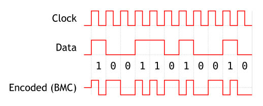
ie: 1 = Long, 0 = short,short OR 0 = Long, 1 = short,short
The important factor is the length of time between transitions (The point at which the wave transitions from high to low or low to high). This image from wikipedia shows how the data is encoded into a wave:
ie: 1 = Long, 0 = short,short OR 0 = Long, 1 = short,short
The important factor is the length of time between transitions (The point at which the wave transitions from high to low or low to high). This image from wikipedia shows how the data is encoded into a wave:
How does it work?
This code is derived from concepts described here and in the VirtualWire Arduino library. The VirtualWire library appears to use a sampling based decode method and '4-to-6 bit' encoding of the data prior to transmission. Comparativly this was more of a learning exercise than a useful project, so is fairly simple, and uses timer based encoding.
Arduino Uno,Mega etc have an 'Input Capture' function that can trigger an interrupt and timestamp it, and I was interested in trying it out for this type of digital communication. This code uses that capability to calculate the difference between transitions and thus decode the binary data. Timer1 is used as a counter to provide the timestamp for the receiver, and used to generate the proper waveform for the transmitter.
Arduino Uno,Mega etc have an 'Input Capture' function that can trigger an interrupt and timestamp it, and I was interested in trying it out for this type of digital communication. This code uses that capability to calculate the difference between transitions and thus decode the binary data. Timer1 is used as a counter to provide the timestamp for the receiver, and used to generate the proper waveform for the transmitter.
Results:
I started off initially using Differential Manchester encoding, and was able to acheive ok results for wireless transmission. The results weren't very useable initially, so I tested a few different methods of modulation, ending up with BMC encoding producing the best results. BMC uses two small transitions for one bit, and one large for the other (0 or 1), so I tried it with only a single small transition, and seem to have the best results so far. I'm not sure if this fits in with another modulation technique, but it is FM either way.
Transmitter:
The data being sent is broken into bits and buffered into memory, while Timer1 is configured to run at a set frequency. A full pulse width is created to encode a 0, and a half pulse width is created to encode a 1, modulating the frequency to send data. The compare-output mode is toggled every cycle to produce the correct waveform, ensuring that positve pulses always follow negative pulses and vice-versa.
Receiver:
The receiver uses the built-in Input Capture mode to timestamp the high and low transitions of the pulses being received, then calculates whether a 0 or 1 was received based on the timestamp. As the bits are received, they are loaded into a temporary byte. If that byte is equal to the 'start byte', it starts buffering data and looks for a 'stop byte'. Once received, it does a simple CRC check to ensure the data is not corrupt, and then makes the data available if successful.
Arduino Sketches:
This seems to work well in testing, up to 32Kbps with a direct connection, and up to 7Kbps at close range with some very cheap 433Mhz VirtualWire capable modules I had sitting around. This was a pretty interesting task, and a good way to understand the general concepts behind the raw signaling that digital devices use to communicate. This is about as far as I plan to take this code for now, so I threw in a bunch of comment s:
RX (receiver) (Timer4, Pin 49 on Mega)
TX (transmitter) (Timer1, Pin9 on Uno,Nano,etc)

