Monday

Arduino: High Speed (8Mhz) Signaling: NTSC TV Output


I recently purchased a cheap 7" color monitor with intentions of using it for FPV flying, but still have not received the transmitting equipment. Of course, in waiting, I began to wonder about interaction with an Arduino, and a few searches led me to the TVOut library, which achieves NTSC video output (B/W) using an Arduino. I downloaded the library, and the more I read through the code, the more I was intrigued by how exactly such fast and accurate timing was acheived.

To give an idea of the requirements, the horizonal sync signal occurs about 15750 cycles/second (every 63.5us), which is relatively easy for an Arduino to produce in itself. In between these signals however, the picture is drawn, which requires much faster signaling and more precise timing, into the Mhz+ range.

In addition to the TVOut library, I also found a simpler form of code here that uses the USART (Serial port) to form the video signal, using each bit in every byte sent to form individual pixels. The main problem I found with this code was timing. It uses sleep mode to help time the video display accurately, but there were still some issues with small video glitches that I could not resolve when replicating the code. It also uses manual writing of the hsync pulse, where the other method uses a timer generated signal.

The first thing to do was to understand the makeup of an NTSC signal. This page provided a straightforward explanation, along with the timing requirements. Then it was on to recreating a hybrid of the code mentioned above, in the simplest possible format. The first part was pretty straightforward, creating horizontal and vertical sync signals. An entire frame consists of 259 horizontal sync signals, and 3 vertical sync signals, which are simply inverted horizontal sync signals to make 262 lines. The following code will produce a sync signal on pin 12, which results in a blank black screen.


#define hLinesPerFrame  262
#define vSync 247
#define hSync 25

volatile unsigned int isrCounter = 0;

void setup(){
  pinMode(12,OUTPUT);
 

  //This sets up the timer to produce the horizontal sync pulses
  //ICR1 is the timer TOP value, OCR1B controls the hSync pulse width
  //OCR1A will control the timing of the video display
  ICR1 = 1019;

  OCR1A = 1;
  OCR1B = 30;
  TCCR1A =  _BV(WGM11) | _BV(COM1B1) | _BV(COM1B0);
  TCCR1B = _BV(WGM13) | _BV(WGM12) | _BV(CS10);
  TIMSK1 = _BV(OCIE1A); 
}


ISR(TIMER1_COMPA_vect){
  ++isrCounter;

  switch(isrCounter){         
          case vSync: OCR1B = 1019-hSync; break;

          case vSync+3: OCR1B = hSync; break;
          case hLinesPerFrame:  isrCounter = 0; break;
        }
  }


void loop(){ 

}

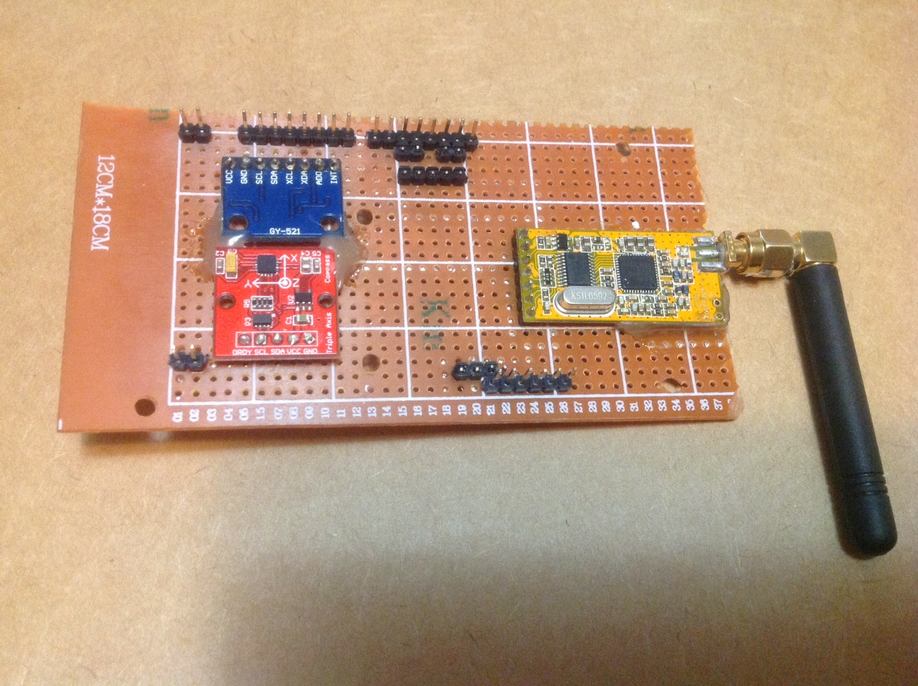
So that part is easy enough, a few lines of code, a 1k resistor from pin 12, and we have a basic NTSC signal with vertical and horizontal sync. Actually creating video will be a bit more complicated, and I've chosen an Arduino Mega due to the amount of SRAM (8K) available, which is needed for higher resolutions.

What I found in experimenting with different methods for timing, is that the timing of interrupts on a standard Arduino board can vary quite a bit. Using sleep mode to idle the board prior to triggering works 98-99% of the time, but still leaves a few interupts coming a bit late, producing glitches in the video. The method used in the TVOut library appears to work the best, as it monitors the counter to trigger at exactly the same time every time. Of course, it is written in assembly, and I made a slight modification to exit immediatly if the wait time has been missed. My explanation may be a slight bit off technically, but should be pretty close:

static void inline wait_until(uint8_t time) {

__asm__ __volatile__ (
    "sub    %[time], %[tcnt1l]\n\t" //Subtract the low byte of TCNT1 from the wait time
    "brmi   102f\n\t"               //If result is negative, we missed it. Branch to 102

 "100:\n\t"                     
    "subi    %[time], 3\n\t"         //Subtract 3 from time
    "brcc    100b\n\t"               //Loop until we get a negative
    "subi    %[time], 0-3\n\t"       //Add 3 back to our value
    "breq    101f\n\t"               //If equal to 0, branch to 101 and delay 1/16 of a uS (No OPeration)
    "dec    %[time]\n\t"            //Decrement our value by 1
    "breq    102f\n\t"               //If equal to 0, branch to 102 and don't delay
    "rjmp    102f\n"                 //Else Jump to the end
 "101:\n\t"
    "nop\n"
 "102:\n"

     :                                 //Output variables (none)
     : [time] "a" (time),              //Input variables
       [tcnt1l] "a" (TCNT1L)

);
 

}

That takes care of the basic signaling, and provides accurate enough timing to begin looking at displaying the video. I chose to use the USART to draw the video, as it simplifies things quite a bit when compared to using functions written in assembly, and should be able to use a baud rate of 8Mhz in Master SPI mode according to the datasheet. The USART also includes a double-buffering capability, which seems to make it more suitable here than using SPI.


We can calculate our BAUD rate, and the required setting for the UBBRn register at maximum speed:

16Mhz / 2(UBRRn + 1)  -->  16 / 2(0 + 1)  -->  16 / 2 -->  BAUD: 8Mhz  UBRRn: 0

Now, to configure the USART, only two lines of code are required in setup() :

  UCSR1C = _BV(UMSEL01) | _BV(UMSEL00); //Set USART to Master SPI mode
  UBRR1 = 0;                            //Baud rate = 8Mhz


Then to create a buffer for the pixel data of 5400 bytes:
    int totalBytes = (400/8) * 108;   
  byte data[totalBytes];

Now, all there is to do is start drawing pixels at the correct time, which (simplified) is done with the following lines of code, which get added to the TIMER1_COMPA_vector interrupt shown above.

wait_until(153);                      //See the assembly function above

UCSR1B |= _BV(TXEN1);                 //Enable USART TX

for (int x =0; x < 400/8; x++){       //Load bytes until we have drawn 1 horizontal line:
  while ( !(UCSR1A & _BV(UDRE1))){ }  //Wait until the USART is ready for more data
  UDR1 = data[x+start];               //Load a byte
}

  
UCSR1B = 0 ;
                                             //Disable the USART TX


...And thats all there is to it. Of course, the last part of it requires a bit more code to control the screen position and count lines, etc, but those are the fundamentals of producing NTSC video with an Arduino. A complete sketch is posted below.

Notes:
a: The timing of the video display in relation to the horizontal sync pulse is very important. It specifically triggers before the h-sync pulse ends so as to have enough time to smooth out variations in triggering.
b: The loading of data into the buffer (UDR1) must be done as quickly as possible, and requires efficient code to work at 8Mhz.
c: Using the USART requires accurate screen positioning due to the pulse created whenever it is enabled. This creates a vertical line, which can be positioned off screen via the wait timing.
d: This code does not use the defined standard timing for parts of the signal, due to better results with slightly modified settings. (ie: 2uS horizontal pulse instead of 4.7uS)
e: The maximum resolution is mainly limited by the memory available, as 1 byte is required for every 8 pixels. (400 x 108 uses 5.4KB)

Summary:
For me, this was an interesting look at the maximum limitations of signaling using an Arduino, and gave me an opportunity to learn a little more about assembly code as well. I found a great tutorial here showing how to view your Arduino code in assembly, and it was a great help in beginning to understand the code behind the code.
All in all, I am pretty happy with the results, as the methods used above seem pretty comparable to the TVOut libary, but with a bit higher resolution. The main benefits of using the USART are simplified code, as the baud rate can be changed to scale the video horizontally, and feeding it data is very straightforward.

The code used to create the above video can be found here and borrows heavily from the code it is based on.


Sunday

A Smaller Custom Arduino Quadcopter


The new 13.5" (34cm) custom quad             

  I've enjoyed building and flying my first custom Quadcopter based on an Arduino and FreeIMU, so decided to build another smaller version. The original really needs some wide open spaces to open up and fly, and I wanted something I could fly in more confined areas. This one is quite a bit smaller, measuring in at 13.5" compared to 21" and is much lighter. It is very similar to the first electronically, but uses a GY-86 module and Arduino Nano for the FC board. The IMU module has a gyro, barometer, compass, and accelerometer. It uses the same APC220 transceiver for control, but a standard RC unit is recommended in most cases.

Video from one of the initial test flights 

  As seen in the pics, the FC board is very simple, and I used the complex design method of 'connect the dots'. Just below the orange transceiver, jumpers can be seen which are used to disconnect it from the hardware serial port when connecting to USB for programming. The other pins shown just beside the Arduino are for connecting the ESCs, one of which powers the board. The Nano is mounted on header pins, so can be easily removed. This one was modelled somewhat after the first, but uses 10mm square carbon fiber booms and no aluminium mounts. The setup in MultiWii is pretty much the same, but with the GY-86 chosen under sensor definitions.


  The 1.5mm sheet was cut into two squares measuring 1.75" x 5" for the main body, and holes were drilled through the booms to bolt them directly between the sheets. Drilling through the booms may not provide the most strength, but with a small well balanced quad, I'm hoping it will hold up. The motor mounts required both a top and bottom plate as well due to the thin layer of carbon fiber in the centre of the boom. Drilling through the carbon fiber sheets completely dulled a standard drill bit as well.

  The two quads side-by-side

  A quick test flight with a 3S 1000maH battery and 3-blade 5045 props provided about 6 minutes of casual flight time, but it should be better with a 2S battery and 6" props according to eCalc. The tool also says the props will stall, but it hovers and moves nicely so not sure about that. The FC board is attached directly to the frame using some nylon standoffs, but vibration is minimal after balancing.
  I had a lot of difficulty trying to balance such small props individually, so admitted defeat and went directly to dynamic balancing. I came across laser balancing in this video and I always keep some spare lasers around (who doesn't?) so I tried it, and the balance was the best I've achieved. I balanced the motors before adding the props/adaptors and re-balancing.


  I had a few issues with these motors, since the mounts are a bit flimsy, and will break if there is excessive vibration. I've since attached the motors using hard rubber between the metal mounts and the carbon fiber to provide some give, and it seems to be working ok so far. Something also seems to have gotten into one of them, tearing apart the wiring, but it was easy to rewind with new magnet wire. Luckily, I bought 5 motors, but I may need to purchase a different type of motor if troubles keep popping up.

Main Parts List:
Quad:
4X HobbyKing Donkey ST2004-1550kv Brushless Motor
4X Propeller Adaptor (Colet Type) 3MM
2X Counter Rotating Three Blade 5x4.5 Propeller
2X Counter Rotating Three Blade 6x4.5 Propeller
4X Turnigy Multistar 10 Amp Multi-rotor Brushless ESC
2X 1000mAh 3S 25C Lipo Pack
2X 1000mAh 2S 25C Lipo Pack
1X 10mm Carbon Fiber Square Tube - 750mm
1X Woven Carbon Fiber Sheet 300x100 (1.5MM Thick)

FC Board:
1X Arduino Nano
1X GY-86 10DOF IMU Module: MS5611 HMC5883L MPU6050
1X APC220 Wireless Serial Data Module

FC Board PinOut:
pin3: front motor
pin9: rear motor
pin10: right motor
pin11: left motor
A4: GY-86 SDA
A5: GY-86 SCL
TX: APC220 RX
RX: APC220 TX   

MultiWii: DIY Wireless LCD Config and PID Tuning using Stick Controls:

   The MultiWii flight control software has the built-in functionality of using an attached LCD for viewing and adjusting settings. This takes it a little further by sending the data wirelessly, which can be very handy for adjusting PID settings and other configuration options while out flying. There are only three main components: Arduino Mega, APC220 wireless data module, and LCD Screen. I might incorporate a smaller screen directly into my controller using this sketch.

 Wireless LCD in configuration menu during testing
  
   This is designed specifically to work with my custom XBox controller and QuadCopter, but will work with standard controllers and MultiWii boards that support or have a serial data transceiver. The status indicator portion does require slight modifications to MultiWii, but the LCD menus will work with the stock software/boards.


Wireless LCD showing status (left,center) and configuration (right)

   Menu navigation takes place via the RC transmitter/controller, so all you have to do is land before entering the LCD menu and adjusting PID or configuration settings. This has been very handy for tuning PID settings in the field and understanding exactly how those changes affect the performance of the aircraft. This could easily be modified to do other things like log or display telemetry, flight or sensor data as well.

Features:
- Long range (up to 1000m with APC220)
- Capable of receiving standard MSP commands and displaying or storing info
- Adjust PID settings wirelessly
- Adjust configuration options wirelessly
- Displays status: 
        - Battery Voltage
        - I2C Error Count
        - Running Time in minutes
        - Flight Mode Indicators

Requirements:
- MultiWii based FC Board w/serial port for wireless serial module (APC220, XBee, etc), or built-in
- DIY Wireless LCD: Arduino Mega + LCD (compatible with LCD library) + APC220(Any wireless serial module)

Hardware Setup:
1. Enable LCD in MultiWii if needed (Config.h)
    a: Un-Comment: #define LCD_CONF, #define LCD_TTY, #define LCD_SERIAL_PORT 3
    b: Set LCD_SERIAL_PORT to the correct port for your transceiver

    c: Upload to FC Board
2. Connect LCD Screen to Arduino Mega and ensure it works with Arduino LCD library. Adjust pins in sketch to match.

3. Attach APC220 or other serial module to Arduino Mega port 3
4. Upload this sketch
5. Enter LCD Menu and adjust as desired
 
LCD Useage:
1. Move Pitch stick up, Yaw right to enter LCD Menu
3. Navigate menus usings stick movements: 

      Pitch Fwd/Back: Prev/Next     Pitch R/L: Value Up/Dn
4. a: Abort/Exit:   Pitch Fwd-Yaw Right

    b: Save/Exit:    Pitch Fwd-Yaw Left 

Sketches:
Wireless LCD
MultiWii (Customized to send additional status data)

Wednesday

Custom Arduino QuadCopter: First Outdoor Test Flights

I've finally had some opportunities to do some outdoor testing, and this is the first such test with a GoPro camera attached. The quad is running on a stock Arduino Mega2560 board, along with some sensors and a digital transceiver. Details of the build are documented here and in previous posts.

This is the first recorded outdoor test-flight, and it goes pretty well at first with some easy flying. I end up trying to do spins and flying around while forgetting to switch from MAG to HeadFree mode, so lose control at the end.

The ESCs are not sealed well from moisture, so needed to be dried out after the snow landing.

The following video is from a 30,000sq ft indoor fly event hosted by Regina Micro-Flyers at the CU EventPlex April 7, 2013:


Tuesday

Digital Data Encoding: Manchester, BMC and Frequency Modulation(FM)

Data generally needs to be encoded to enable the transmission of digital data across various mediums, and I've always had an interest in radio/wireless communication, so this was pretty much going to happen eventually. I've used some VirtualWire modules, and took an interest in how they work and how to apply the concepts learned from that code and other sources. This lead to the following sketches which encode data using a modified version of Biphase Mark Code (BMC) encoding, which is a specific form of Frequency Modulation, (FM) used to transfer digital data.


A Quick Look at BMC Encoding:

If you look up Biphase Mark Code online, you may be lead to information on Differential Manchester encoding, which has fundamental differences from BMC. You will also generally find excessively complex explanations of how it works, but it is actually quite simple. In the end, you basically send a bunch of binary data (1 and 0), and represent that data either with 1 long period or 2 short periods:

ie: 1 = Long, 0 = short,short  OR  0 = Long, 1 = short,short

The important factor is the length of time between transitions (The point at which the wave transitions from high to low or low to high). This image from wikipedia shows how the data is encoded into a wave:


How does it work?

This code is derived from concepts described here and in the VirtualWire Arduino library. The VirtualWire library appears to use a sampling based decode method and '4-to-6 bit' encoding of the data prior to transmission. Comparativly this was more of a learning exercise than a useful project, so is fairly simple, and uses timer based encoding.

Arduino Uno,Mega etc have an 'Input Capture' function that can trigger an interrupt and timestamp it, and I was interested in trying it out for this type of digital communication. This code uses that capability to calculate the difference between transitions and thus decode the binary data. Timer1 is used as a counter to provide the timestamp for the receiver, and used to generate the proper waveform for the transmitter.


Results:

I started off initially using Differential Manchester encoding, and was able to acheive ok results for wireless transmission. The results weren't very useable initially, so I tested a few different methods of modulation, ending up with BMC encoding producing the best results. BMC uses two small transitions for one bit, and one large for the other (0 or 1), so I tried it with only a single small transition, and seem to have the best results so far. I'm not sure if this fits in with another modulation technique, but it is FM either way.

Transmitter:

The data being sent is broken into bits and buffered into memory, while Timer1 is configured to run at a set frequency. A full pulse width is created to encode a 0, and a half pulse width is created to encode a 1, modulating the frequency to send data. The compare-output mode is toggled every cycle to produce the correct waveform, ensuring that positve pulses always follow negative pulses and vice-versa. 

Receiver:

The receiver uses the built-in Input Capture mode to timestamp the high and low transitions of the pulses being received, then calculates whether a 0 or 1 was received based on the timestamp. As the bits are received, they are loaded into a temporary byte. If that byte is equal to the 'start byte', it starts buffering data and looks for a 'stop byte'. Once received, it does a simple CRC check to ensure the data is not corrupt, and then makes the data available if successful.


Arduino Sketches:

 This seems to work well in testing, up to 32Kbps with a direct connection, and up to 7Kbps at close range with some very cheap 433Mhz VirtualWire capable modules I had sitting around. This was a pretty interesting task, and a good way to understand the general concepts behind the raw signaling that digital devices use to communicate. This is about as far as I plan to take this code for now, so I threw in a bunch of comment  s:

RX (receiver)  (Timer4, Pin 49 on Mega)
TX (transmitter) (Timer1, Pin9 on Uno,Nano,etc)


QuadCopter: Current Summary, Docs and Info 


The quad, controller, and camera


Flight Control Board

The flight control board is based on FreeIMU and built onto an Arduino Mega 2560 running MultiWii. The main goals were to build a customizeable and affordable quadcopter using mainly open source hardware and software, and learn a bit about how it all works. Bugs and design issues seem to have been worked out now, so it looks like this will be the base design for my board. Video

Since it is all open source, adding additional custom components to control lights, sound, servos, etc. is about as easy as it gets. For anybody already familiar with Arduino, it's just a matter of  choosing what customizations to add.

The top picture on the right shows the simplicity of  the FC board, using only a few modules. A previous mock-up of the board was scrapped due to some simple design flaws. The current version attempts to address some of those problems:

a: Although the shield fits tight, secure mounting is a must, and nylon standoffs are used to secure the shield to the Arduino.

b: Here I am using a cheap, single sided prototyping board, but we'll see how long it lasts...

c: The first mock-up used the female header pins as shown on the right of the bottom pic, but they aren't made for Arduinos (too thin), and caused I2C errors and subsequent crashes. The header pins shown on the left are thicker and fit snug every time.

d: The GPS module was left out since GPS nav won't be something I'll be using right away.

The ESCs connect to pins exposed on the top of the board, which are hard to see since the angle of the bottom pic purposely hides my shoddy looking soldering work. The Arduino gets fastened to the frame using rubber mounts taken from broken CD/DVD players to minimize vibration.


Notes:

FC Board:
The board is intially based on a FreeIMU board as mentioned previously, and is actually pretty simple to build at this point, with only 3 modules. The HMC5883L magnetometer module is connected to the aux. I2C lines of the MPU-6050, and running on 3.3V. An APC220 module is connected to the fourth serial port (serial3), and a GPS module can go on serial2 or via I2C if desired. The best part of the flight controller and quadcopter is that it is all based on open source software and hardware, so customization and prototyping like this is actually possible without spending huge amounts of money or time.

FC Board/Arduino Mega Connections:
pin2: front motor
pin3: rear motor
pin5: right motor
pin6: left motor
pin14: APC220 RX pin
pin15: APC220 TX pin
pin16: GPS RX pin
pin17: GPS TX pin
pin18: MPU6050 interrupt
pin20: MPU6050 SDA (I2C)
pin21: MPU6050 SDL (I2C)
pinA0: Voltage divider (battery monitor)
MPU6050: Aux SDA to HMC5883L SDA
MPU6050: Aux SDL to HMC5883L SDL


Main Parts:
1x Turnigy Talon carbon fiber frame
4x Turnigy 20Amp MultiStar ESCs
1x Turnigy ESC programmer
4x NTM Prop Drive Series 28-26A 1200kv/250W Motors
2x Slow Fly 8045 propellers
2x Slow Fly 8045R propellers
1x 4000mAh 3S LiPo battery pack
1x Arduino Mega
1x GY-521 Gyro Module (MPU-6050
1x HMC5883L Magnetometer module 
1x APC220 serial data wireless transceiver
Uses Modified XBox controller for RC (previous post)


XBox Controller:
Prev post. Uses the MultiWii RCSerial protocol
Quad can easily be controled by a PC via RCSerial protocol and APC220 transceiver

Frame/Physical Assembly:

Since the controller and FC board are both custom made, I had to code and then debug the controller during flight in some cases, and had no failsafe at the time. The initial assembly of the central parts of the frame used all nylon bolts. This was to prevent damage to the frame and motors when big crashes happened, since parts would usually break away before breaking or bending much. It currently uses a combination of metal and nylon connectors to provide rigidity and allow for some give on big impacts. As can be seen in the picture above, I have also made my own motor mounts.

ESC Calibration:

One of the problems I ran into in some of the first flights was individual motors cutting out seemingly randomly. The quad uses 20A Turnigy MultiStar ESCs, and gives a choice between slow-down of motors, and hard cutoff when the voltage is low. This caused a bit of frustration since the motors would start cutting out when the voltage was low, regardless of the setting via programming card.

I was confused by the MultiWii calibration code at first since, according to the ESC manual, it would basically just set the programming of the ESCs to the LiPo battery setting, and that hardly seemed like 'calibration':

ESC Programming:
a: Power ESCs on while receiving max throttle signal
b: These ESC will beep accordingly, move throttle to min to select what option to set in the programming 

The ESCs apparently use this interaction for calibration as well, and it made a big difference once I programmed them this way. The motors seemed to sound a bit smoother afterward, and they slow down nicely to force a landing once the battery is low.

Always remove your propellers before uncommenting this line in 'config.h':
#define ESC_CALIB_CANNOT_FLY 

Propeller Balancing:

Another important factor that was initially overlooked was propeller balancing. This made a big difference in the stability of the craft, as well as reducing vibrations. I followed this tutorial and had some good results on my first shot at it. Videos from the previous post show the vibration evident from unbalanced propellers, and a motor wire breaks in the second one, likely related to the vibration issues.

MultiWii Config and GUI:

The videos in the previous post were shot using the PID settings shown in the pic to the right and with the low-pass filter enabled for the MPU-6050 at 20Hz in 'config.h'. Higher values for the filter makes for 'tighter' controls, but is more susceptible to vibration and affects PID. Mitigating vibration issues should allow a higher setting. 

MultiWii Code:
Code base is MultiWii_dev_r1240
Uses slightly modified version, but can work with original:
  • Supports serial rc cmds with smaller payloads
  • Supports failsafe when using serial rc
  • Supports basic monitoring during flight via processing gui and existing transceiver (prev. post)
  • Still unsure whether to remove or work with test code to control a music player from alarms and controls, so left it in for now (alarm buzzer timing is changed)
  • Longer delay for ESC calibration code specific to MultiStar ESCs (see esc manual below)


Reference Material:
MultiWii - Code w/Modifications
MultiWii - Arduino Mega pin layout
MultiWii Wiki


Auto Analog Audio & NRF52840: Now working on non-Mbed cores

 Auto Analog Audio & NRF52840: Now working on non-Mbed cores Playing around with the AAAudio library So I finally decided to make the ne...